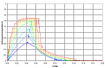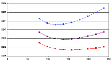
L&G Software first developed a mathematical calculation model for pneumatic cylinders with damping effects and used it in a simulation model of the existing cross-stacker. The dampers in the simulation model could be positioned through a comparison with real measurements on the object. After that, the dampers and their settings were implemented into a simulation model of the new cross-stacker. Different attachment points for the cylinders resulted in different velocity progression or behavior. The simulation shows all oscillations and vibrations.
Müller Martini in Zofingen, Switzerland
Optimization of a simple mechanical system
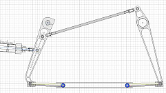
Müller Martini is a maker of systems used in the printing industry. In 2003, a new cross-stacker that was supposed to replace and improve on its predecessor in terms of performance was developed. A cross-stacker is an instrument that catches and organizes printed materials with a fork and then bundles them. As with many technical developments, the goal is maximum performance combined with an acceptable “lifespan” and minimal cost. The critical components of the cross-stacker are the two arms of the fork, which have to be opened and closed as quickly as possible with pneumatic cylinders. This keeps the machine’s downtime to a minimum.
What this example shows:
Often, even seemingly simple mechanical systems can’t be so easily optimized without the right simulation tools. At least not in the planning stage. If several variable influences play a role, the problem quickly becomes multi-faceted and can no longer be solved with simple analytical calculations .